Pavement design brief for Polycrete® Channels
– Specification Briefing Document
An installed ACO Drain System should incorporate the following:
- Correct channel type and size.
- Correct grate type. (All grates must be fully locked down in trafficable applications.)
- Correctly designed concrete encasement of minimum compressive strength 25 MPa.
It is the customer’s responsibility to ensure the concrete encasement is suited for the application and is designed/approved by the project’s engineer.
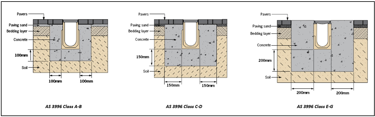
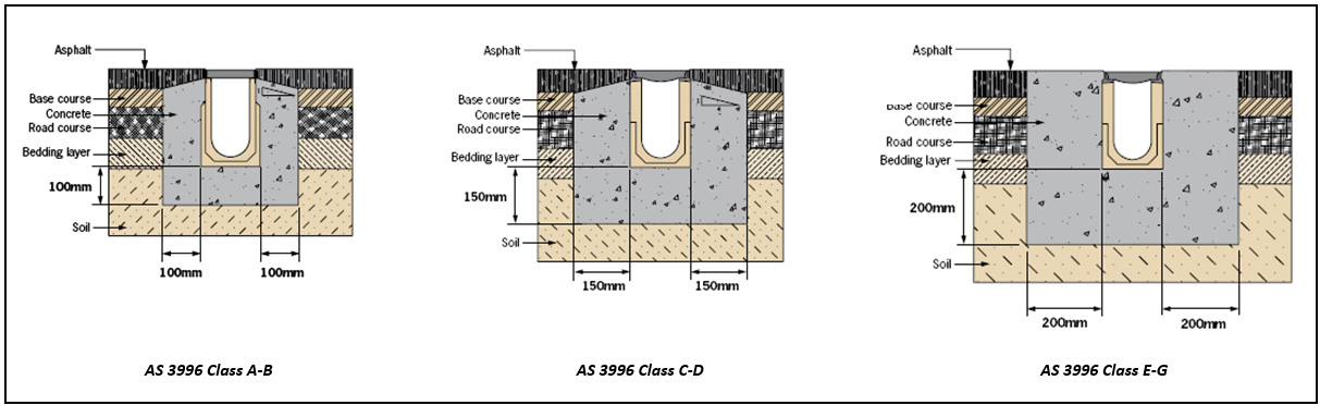
Systems are typically installed in concrete slabs, flexible pavements and block pavements. ACO Drain Systems must be encased in a concrete surround that is both durable and conform to at least the minimum dimensional requirements, shown in ACO’s recommended installation drawings
These illustrations are a guide for average ground conditions only. Specific site conditions may require an increase in these dimensions and/or the addition of reinforcement.
If more than one pour is cast to form the concrete surround, each pour must be adequately bonded to the other. This is for structural continuity.
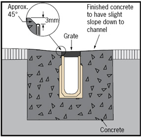
The top of the encasement adjacent to the pavement must be above the grate level (approximately 3mm), this ensures all liquids drain into the channel and that the channel edge is protected against direct traffic loads, see adjacent illustration (left). The same applies for pavements laid up to the channel edge.
The encasement must be designed to support the channel system under load and isolate it from stresses derived from live loads and from the thermal movement of any adjacent slabs. Care must be taken during the curing regime to ensure no gaps appear between the drain channels and the encasement. Shrinkage reinforcement may be required.
Concrete Slabs
What is Thermal Movement?
Concrete moves with changes in temperatures, expanding when heated and contracting when cooled. While the amount of movement is not significant, stresses induced by thermal expansion can be.
If the concrete slab was free to move without restraints, stresses at the edge of the slab would be low. However, if ACO Drain Systems are positioned to restrain slab movement, the stresses would be high and therefore the channel system would be susceptible to damage.
The type of aggregate used in the concrete is the major factor influencing thermal expansion. The following table is from “SAA HB 64-2002 Guide to Concrete Construction – Table 19.5 Coefficients of expansion”, published by Cement & Concrete Association of Australia.

The following calculation shows the effects of thermal expansion on a concrete slab with the change in temperature on a typical day.
Assuming:

Thermal Expansion = (0.0095 x 15 x 40) = 5.7mm
If the concrete slab is restrained from movement in all directions, then cumulative stresses induced on the restraints can be calculated using the assumptions above:
Strain = ((9.5 x 10-6) x 40) = 0.00038
Stress = (25,000 x 0.00038) = 9.5 N/mm2
Equating to a force per metre of:
Force = (9.5 x 200 x 1000) = 1,900,000N = 1,900kN (approximately 194 tonnes)
No surface drainage system would be able to withstand these forces and so the encasement supporting it must either be structurally designed to direct the stresses away from the drain or be physically isolated with the inclusion of longitudinal expansion joints.
Expansion joints
Expansion joints are a cost effective way to cater for the thermal expansion of slabs. The joints are either longitudinal (running parallel to the channel haunch) or transverse (cutting across channel haunch and base) to the trench drain.
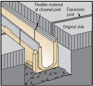
Longitudinal expansion joints should be continuous and flexible. The joints must be provided at a depth equal to the adjacent slab between the concrete encasement and adjacent slab, see illustrations below. The minimum distance between the channel edge and expansion joint may be varied to suit the concrete surround width up to a metre from the channel.

Transverse contraction/expansion joints (cutting across the trench run) to prevent surface cracking in the concrete slab may be required.
Ideally, such joints should be positioned at channel joints. Alternatively, a cut may be made at the appropriate location along the channel and sealed with flexible sealant, see adjacent illustration (right).
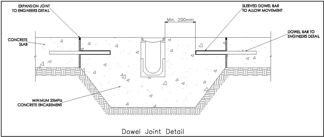
Dowels may be specified by the engineer if differential settlement is a concern.
If the joint is dowelled, effective debonding should be provided. Dowels must be horizontal.
Reinforcement
The concrete encasement may require reinforcement for a number of reasons. Three common reasons are discussed below.
- The engineer may choose to reinforce the encasement to increase its flexural strength. This is not uncommon for long trench runs particularly if ground movement is anticipated.
- Reinforcement may also be incorporated for the control of cracking along the encasement.
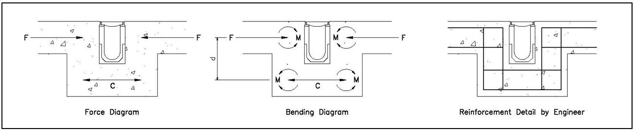
- In concrete slabs if longitudinal expansion joints are not a practical solution, then the reinforcement design must be carefully considered. This is because very high forces can arise from thermal movement in the concrete slab and the ACO Drain System is not designed to restrain these forces. The encasement supporting the system must either be structurally designed to direct the stresses away from the drain or physically isolated with the inclusion of longitudinal expansion joints.
Considering this scenario, the force (F) from thermal movement must be transferred via the haunch to the concrete base below the ACO Drain. Even if the concrete base below the ACO Drain can take the compressive forces (C) the force in the expanding slab is not in the same plane. Thus a couple, or moments (M) will occur. In order to transfer the force (F) into the concrete base below, steel reinforcement must be designed to withstand the bending stress (M) produced by the couple (F x d) and transfer it away and below the trench.
Note, the deeper the trench the higher the bending stresses, resulting in a heavier reinforcement solution.
If steel reinforcement is required, ACO recommends seeking structural engineering advice.
Flexible Pavements
For applications up to Load Class D, asphalt can be applied directly up to channel edge, see illustrations below for concrete haunch details.
The channel edge should be protected before the application of asphalt as it is exposed at this stage of the installation and could be damaged.
CAUTION: When rolling asphalt, care should be taken not to damage channel edge or grate. Small asphalt paving machinery should be used in the area directly adjacent to the channel edge rail.
Block Pavements – Pavers
For applications up to Load Class D, pavers can be installed up to channel edge, see illustrations below for concrete haunch details.
The paver course adjacent to the channel MUST be fully bonded to the concrete haunch. The bonding prevents movement of pavers and possible damage to channel. Subsequent pavers, not in proximity to the trench drain, can be bedded on compacted sand.